Home|
Syllabus|
Notes|
Assignments
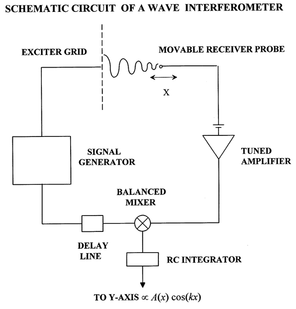
Schematic of a Wave Interferometer Circuit
Plasma Physics Laboratory
R. L. Stenzel, Winter '97

Typical interferometer circuit.
Here are the basic features of the wave interferometer:
- A continuous wave (CW) signal generator is driving a
plane grid in a plasma so as to excite ion waves.
- The wave is observed in the oscillating current of a
Langmuir probe, biased to the electron saturation current,
hence measuring density oscillations. A narrow-band
amplifier is tuned to the signal frequency so as to improve
the signal-to-noise ratio.
- A reference signal of same frequency as the wave signal
is delayed and applied to a double-balanced mixer. The latter
multiplies the reference signal with the wave signal. An R-C
integrator filters out the dc component of the product which is
given by A(x)cos(kx-phi), where A(x) is proportional to the wave
amplitude and phi is the phase shift of the delay line. This signal
is applied to the Y-axis of a recorder and/or to the analog-to-digital (AD)
converter in the computer.
- The probe position is measured with a potentiometer which
gives a dc voltage V proportional to x. This voltage is applied
to the X-axis of the recorder or a second AD converter in the computer.
- The purpose of the phase shifter is to identify the direction of
wave propagation and to distinguish propagating from standing waves.
If the delay is increased the interferometer traces shift in the
direction of wave propagation. For standing waves (coskx cosphi), the
phase does not shift but the amplitude varies sinusoidally with delay.
Home|
Syllabus|
Notes|
Assignments
Page maintained by
R. L. Stenzel and/or
J. M. Urrutia
Copyright © 1997, The Regents of the University of California. All Rights Reserved.
Last Update: 5 March 1997


