The following photographs were made in the Physics 180E undergraduate
laboratory course in plasma physics by
Professor
Reiner L. Stenzel. They are designed to
demonstrate the single particle motion in electric and magnetic
fields. A weak electron beam of typically 100 eV, 1-10 mA is
injected from an oxide-coated cathode into a low pressure
(0.2 mTorr) argon gas. The beam partially ionizes the gas. The
background plasma has a potential close to that of the grounded
chamber wall. The beam electrons are accelerated by an electric
field mainly concentrated in the cathode sheath. The trajectory
of the beam electrons is visible due to light excitation when
the beam electrons collide with argon atoms. No visible light
is produced when the electron energy is below typically 10 eV.
Several basic phenomena can be inferred from the following
pictures. These were taken with a Rolleiflex camera, 400 ASA,
black and white film, with up to one minute exposure time.
|
|
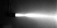
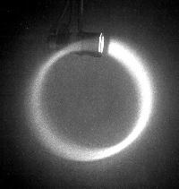
Fig. 1. A 100 eV electron beam is injected into a neutral gas
without applying external electric or magnetic fields. The beam
light starts very close to the cathode indicating that the
electrons acquire their full energy in a very thin cathode
sheath. Thus, the self-produced plasma acts as an anode. The
initial beam convergence indicates concave equipotential
surfaces near the cathode, presumably due to a radial density
gradient. The beam scatters by collisions and beam-plasma
instabilities.
(Larger image: 114,808 bytes, 913×461 pixels).
|
|
|
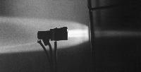
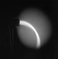
Fig. 2. The beam is injected against a negatively biased grid.
When the bias voltage is slightly larger than the cathode
voltage most of the beam is reflected but a few electrons are
transmitted. Note that the equipotential surface near the grid
is not plane but convex. This causes an angular spread of the
reflected electrons. Electrons in the center of the beam are
normal to the sheath and can pass the grid when their energy
exceeds the potential energy of the sheath.
(Larger image: 111,597 bytes, 927×475 pixels).
|
|
|
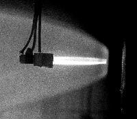
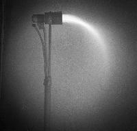
Fig. 3. Beam injection against a very negatively biased grid
which reflects all electrons.
Note dark sheath near grid where the electron energy is
decreased below 10 eV.
The electrons stagnate in the dark sheath and form a
convex equipotential surface.
This causes the reflected beam to be highly divergent.
(Larger image: 249,846 bytes, 836×732 pixels).
|
|
|
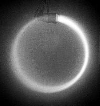
Fig. 4. A 100 eV electron beam injected perpendicular to a dc
magnetic field. The sense of the cyclotron orbit implies that
the magnetic field points into the plane. From the beam energy
and the cyclotron radius the field strength can be calculated.
Note that the beam light weakens with propagation distance
(Larger image: 229,104 bytes, 767×809 pixels).
|
|
|
Fig. 5. A low energy beam is injected across a magnetic field
as in Fig. 1. The cyclotron radius is decreased. Note the dark
gap between the cathode and beam onset. In this sheath region
the electrons still have insufficient energy for light
excitation.
(Larger image: 124,601 bytes, 575×609 pixels).
|
|
|
Fig. 6. A low energy beam is injected against a decelerating
electric field. As the beam energy falls below 10 eV the light
emission stops. The beam and current continue to flow through
the dark region.
(Larger image: 95,390 bytes, 663×669 pixels).
|
|
|
Fig. 7. At high neutral pressures the injected electron beam
rapidly spreads. The electron mean free path can be inferred
from the beam decay.
(Larger image: 206,348 bytes, 799×767 pixels).
|
|
|
Fig. 8. Electron motion in crossed electric and magnetic
fields. The trajectory is a cycloid, i.e., a superposition of a
circular motion and a constant drift to the right. The cyclotron
orbit implies a magnetic field direction into the plane and the
E×B drift implies that the electric field
points downward. From
the known beam energy the field strengths can be obtained from
cyclotron radius and guiding center drift.
(Larger image: 147,526 bytes, 863×601 pixels).
|
|
|
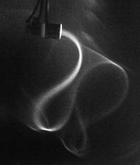
Fig. 9. Mirror reflection of a weak electron beam in a
nonuniform magnetic field. The beam is injected oblique to the
field lines which converge to the right. Due to the adiabatic
invariants (energy and magnetic moment) the parallel energy is
converted into perpendicular energy at which point the particles
reflect. Alternatively, the parallel motion is decelerated by
the repelling force of an increasing magnetic field.
(Larger image: 173,651 bytes, 850×941 pixels).
|
|
|
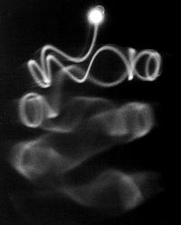
Fig. 10. Mirror reflection of a stronger electron beam in a
magnetic field which converges to the right. Note that the
guiding center (axis of spiral) of the reflected beam does not
coincide with that of the incident. This is due to the gradient
and curvature drift in a nonuniform field.
(Larger image: 215,620 bytes, 1015×761 pixels).
|
|
|
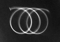
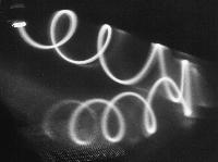
Fig 11. Multiple reflections of an oblique electron beam in a
mirror magnetic field. The cyclotron motion is the fastest
periodic motion, followed by the slower bounce motion between
the mirror points. Gradient and curvature drifts cause a third,
slowest rotation azimuthally around the mirror axis. This is
the classical charged particle motion in the ionosphere in
Earth's magnetic dipole field. Collisions and other scattering
processes diffuse the beam.
(Larger image: 188,031 bytes, 817×1015 pixels).
|
|
|
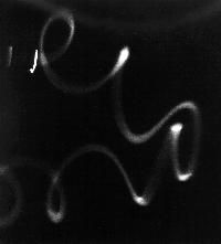
Fig.12. Electron beam injected into a nonuniform magnetic field
with a null line. The beam meanders along a magnetic null line
pointing diagonally down to the right. Note the reversal of the
cyclotron rotation as the magnetic field reverses to either side
of the neutral line. Such meandering and figure-eight
trajectories have been studied theoretically in the problem of
magnetic reconnection occuring in the magnetosphere and on the
sun.
(Larger image: 190,012 bytes, 761×893 pixels).
|
|