Current biological sensing
techniques commonly rely on optical detection principles that are inherently
complex, requiring multiple steps between the actual engagement of
Current biological sensing
techniques commonly rely on optical detection principles that are inherently
complex, requiring multiple steps between the actual engagement of
the analyte and the generation of a signal, multiple reagents, preparative
steps, signal amplification, complex data analysis, and relatively large sample
size. The techniques are highly sensitive and specific but more difficult to
miniaturize. Electronic detection techniques may offer an alternative, but
their potential has not yet been explored fully. Field effect transistors
(FETs) fabricated using semiconducting single
wall carbon nanotubes (nanotube FETs, NTFETs) have been extensively studied.1,2
Such devices have been found to be sensitive to various gases, such as oxygen
and ammonia, and thus can operate as sensitive chemical sensors. The mech-anism
responsible for the change of device characteristic is thought3 to be a charge-transfer
reaction between the analytes and the nanotube. NTFET devices,3,4
together with devices based on nanowires,5 are also promising
candidates for electronic detection of biological species. Various groups
have examined the conformational compatibility - driven by size issues as well
as hydrophobic effects-between proteins and carbon nanotubes using
streptavidin, and found that the protein is able to crystallize in a helical
conformation around multiwall carbon nanotubes.6. We have also shown7 that functionalization of the
nanotubes with carboxylic groups, thereby rendering them more hydrophilic, does
not lead to protein attachment, thus opening up the avenues for specific-ity.
Researchers have also made^v4 some attempts at func-tionalizing single-wall
carbon nanotubes to make them biocompatibile, capable of recognizing proteins
by using
*
Corresponding author. E-mail: astar@nano.com.
10.1021/nl0340172
CCC: $25.00 Ó 2003 American
Chemical Society
Published on Web 03/05/2003
|
|
 On leave from Department of Physics,
University of California, Los Angeles.
On leave from Department of Physics,
University of California, Los Angeles.
noncovalent binding between a
bifunctional molecule and
the nanotube to anchor a bioreceptor molecule with a high degree of control and
specificity.
In this communication we report taking
these advances one step further, by using a sensor architecture that allows the
detection of protein-receptor interactions (using biotin-streptavidin binding
as an example) and, at the same time, reduces or eliminates nonspecific protein
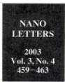
binding. Figure 1 schematically depicts a sensor architecture that uses a NTFET
as a transducer; it is covered with a polymer coating that
has hydrophilic properties and onto which biotin is attached. Polymer
functionalization in this sensor architecture has several advantages. First,
the polymer is used to attach molecular receptor molecules to the sidewalls of
nanotubes. Several examples of covalent chemical attachment of bio-logical
molecules to nanotubes, including proteins and DNA, have been recently
published. 8 Covalent modification, how-ever, has the
disadvantage that it impairs physical properties of carbon nanotubes. For these
reasons we have employed a supramolecular approach, namely, the noncovalent
function-alization of carbon nanotubes by employing polymer coat-ings. 9 Second,
polymer coatings have been shown to modify the characteristics of nanotube FET
devices, and thus the coating process can be readily monitored. In particular,
coating NTFETs with polyethylene imine (PEI) polymer was
found10 to shift the device characteristic from p-to n-type,
presumably due to the electron-donating ability of amine groups in the polymer.
Third, the polymer coating could be used to prevent nonspecific binding of
proteins. A variety
of polymer coatings and self-assembled monolayers have
been used to prevent binding of undesired species on surfaces for biosensor and
biomedical device application. 11 Among
the various available polymers for coating, poly(ethy1ene

glycol) (PEG) is one of the most effective and widely used.
glycol) (PEG) is one of the most effective and widely used.
This layer, due to its hydrophilicity, reduces the affinity of
nanotubes toward protein binding.
We have chosen the
biotin - streptavidin binding to
demonstrate the effectiveness of the device architecture. This binding serves
as a model system for protein interactions,12
has been extensively studied, and the binding is well
understood. In our procedure, after incubation, the device
was washed and dried, and the device characteristics were
examined after drying. While we have explored the device
response in a buffer, our objective here is to examine the changes of the
device characteristic, brought about by the
different chemical and biological modifications on the
electronic response, such direct correspondence being some-
what obscured in a buffer environment.13
PET devices
with nanotubes as the conducting channel
were fabricated using nanotubes grown by chemical vapor
deposition (CVD) on 200 nm of silicon dioxide on doped
silicon from iron nanoparticles with methanehydrogen gas
mixture at 900 OC; electrical leads were patterned on top of
the nanotubes from titanium films 35 nm thick capped with
gold layers 5 nm thick, with a gap of 0.75 pm between source
and drain. Multiple nanotubes connected the source and drain
electrodes, with the individual tubes varying from
metallic
to semiconducting.14 Consequently, a range of device modulations (expressed as the ratio of the "on"
to the "off source - drain current, measured at -10 V and +10 V gate
voltage, respectively) were observed. The devices displayed
p-type transistor behavior, as has also been observed by others. 1,2 In this paper we have examined the dependence of
the source - drain current, Isd, as a function of the gate voltage Vg, Isd (Vg),
measured from +10 V to -10 V, and we refer
to this response as the "device characteristic". After conduct-
ing initial electrical measurements to establish the device
characteristic, the substrates were submerged in a 10 wt %
solution of poly(ethy1ene imine) (PEI, average molecular weight -25 000, Aldrich) and poly(ethy1ene glycol) (PEG,
average molecular weight 10 000, Aldrich)
in water over-
460
Nan
Lett.,
Vol. 3, No. 4., 2003
|
|
the oligomer can be regarded as a
duplex held together
by identical base pair interaction energy at the different sites. We are not
aware of experiments which address the situation where differences between
binding energies as-sociated with different base pairs and other complications
do not arise and which thus would allow the experimental test of simple, but
important descriptions of the melting transition.
For finite oligomers,
the following argument can be made: the binding energy between two bases
located at the end of the molecule is smaller than the binding energy for pairs
away from the ends, consequently the unbinding occurs most likely
night, followed by thorough rinsing
with water. Commercial polyethyleneimine (PEI) was used; this form is highly
branched, has a molecular weight of about 25 000, and contains
about 500 monomer residues. About 25% of the amino groups of PEI are primary
with about 50% secondary, and 25% tertiary. A thin layer (<l0 nm) of polymer
material coated the devices, as observed by atomic force microscopy. The
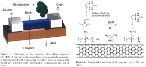
polymer-coated devices were biotinylated by submerging them in a 15 mM DMF solution
of biotin-N-hydroxysuc-cinimide ester (Sigma) at room temperature. This
compound readily reacts with primary amines in PEI under ambient conditions,
leading to changes of the device characteristic
as will be discussed below. After soaking overnight, devices were removed,
rinsed with DMF and deionized water, blown dry in nitrogen flow, and dried in a
vacuum. Figure 2 depicts the scheme by which biotin was attached to the polymer
coating. The biotinylated polymer-coated devices were exposed to the 2.5 µM solution of
streptavidin15in 0.01 M phosphate buffered saline (pH = 7.2, Sigma) at room
temperature for 15 min. Subsequently, the devices were thoroughly rinsed with
deionized water and blown dry with nitrogen. Several control experiments have
also been per-formed in order to demonstrate the effectiveness of the polymer
layer in the prevention of nonspecific binding.
An atomic
force microscope (AFM) image of one of the devices after exposure to
streptavidin labeled with gold nanoparticles is shown in Figure 3. Light dots
represent gold nanoparticles (10 nm), and thus indicate the presence of
streptavidin. Based on the image, we conclude that strepta-vidin is effectively
attached to the nanotubes, due to the strong adsorption of the PEI polymer to
the sidewalls of the nanotubes, which was biotinylated after deposition. With a
nanotube length of 800 nm and a gold sphere diameter of
10 nm, it is expected that, upon full coating, there are approximately 80
streptavidin molecules in direct interaction with the nanotube conducting
channel. (This assumes that,
on the average, one streptavidin molecule per gold nano-particle is attached to
the nanotube.)
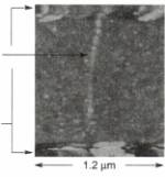
Figure 3. AFM image of
the polymer-coated and biotinylated
NTFET after exposure to streptavidin labeled with gold nanopar-
ticles (10 nm diameter).
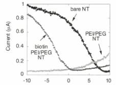
Gate Voltage (V)
Figure 4. Gate voltage dependence of the source-drain
current Isd
of a typical device before
and after PEIPEG polymer coating and after biotin attachment to the polymer
layer.
Next we discuss the change of the device characteristic
in response to the steps we have taken. The device characteristic before
chemical modification is p-type, in an ambient environment, presumably due to
exposure to oxy-gen.16 Coating the device with the mixture of PEI
and PEG polymers results in an n-type device characteristic (Figure
4). This effect, which has been observed10 before,
probably results from the electron donating property of the NH2
groups of the polymer. The electronic characteristic of the device after 18 h
of biotinylation reaction is also depicted in Figure
4. Attachment of biotin is through
covalent binding to the primary NH2 group, thereby reducing the overall electron
donating function of PEI and leading to a device character-istic that is consistent with removal of electrons from the
device. As only the primary NH2 sites are involved in binding to biotin, the p-type
conductance observed before coating is not fully recovered.17
Nano Lett., Vol. 3, No. 4, 2003 461
|
|
The effect of exposing the biotinylated polymer-coated device to a
streptavidin solution and the control experiments (conducted on different
devices) are shown in Figure 5.
Figure 5a shows a striking loss of source-drain current for negative gate
voltages after exposure to streptavidin and consequent streptavidin-biotin
binding with little evidence for the shift of the device characteristic toward
negative or positive gate voltage. Several control experiments were performed
to demonstrate the effectiveness of the device architecture in avoiding false
positives and in detecting specific protein binding. First, we have exposed the
uncoated NTFET device to streptavidin and have found a change of the device
characteristic, as shown in Figure 5b, indicating attachment of streptavidin to
the device. Note, however, that in this case the primary effect is the shift of
the device characteristic toward negative gate voltage. In contrast, when the
device was polymer-coated, but not biotinylated, no changes occurred upon
exposure to streptavidin (Figure 5c). This suggests the effectiveness of the
polymer coating in preventing direct, nonspecific interaction of streptavidin
with the nanotube. Finally, addition of a streptavidin in which
the biotin-binding sites were blocked by complexation with excess biotin
produced essentially no change in device characteristic of the biotinylated
polymer-coated device (Figure 5d).
Several
conclusions on the effect of biomolecules on the device electronics can be
drawn. First, exposing the bare, uncoated device to streptavidin leads to the
shift of the transconductance toward negative gate voltages, thereby rendering
the device less p-type, with little reduction in the magnitude of the
transconductance. This indicates that the primary effect of the
nanotube-streptavidin binding is a charge-transfer reaction with streptavidin
donating electrons to the nanotube.16
Biotin-streptavidin binding has a different effect; in this case the Isd is reduced.
We suggest that upon streptavidin-biotin binding, geometric deformations occur,
leading to scattering sites on the nanotube, and thus to
reduced conductance. At the same time the device charac- teristic is modified
only for negative gate voltages (see Figure 5a), leaving the transconductance
in the positive gate voltage region unaffected. We have observed17similar
features in devices to which charge carders were deposited, and we have argued
that the observation is due to localization (delocal-ization) of positively
(negatively) charged ionic entities by a negatively (positively) charged
surface. Such a mechanism may also be effective here, and the mechanism may
open
the way for electronic modification of bioreactions.
With
improvements in NTFET devices, they may also be rendered sensitive enough that
single protein detection and monitoring can be achieved. As can be inferred
from Figure 5a, the total change in transconductance exceeds the noise level by
a factor of 10. According to an AFM image of the device (Figure 3), there are
about 100 gold nanoparticles,
and approximately 100 protein molecules (assuming one protein per gold
nanoparticle binding to the tube) in close proximity to the carbon nanotube.
Combining these two numbers, our current detection level can be estimated to be
of the order of 10 streptavidin molecules.
Similar detection sensitivity
can be inferred from experiments we have conducted on uncoated nanotubes
incubated with streptavidin (Figure 5b). This is in contrast to the relatively
modest
change observed in devices where the
active element is a nanowire5 -
a channel with a substantially larger cross
section.
Electronic
sensing using devices with nanotubes as the conducting channel offers several
advantages. Such sensors are small and fast, and the active detection area is
sized for individual proteins or viruses. These sensors are extremely
sensitive, as all the current passes through the detection point. Most
importantly, at a later stage the devices can be made specific to individual
molecules; potentially their response to different species can be varied in a
controlled way using chemical and biological functionalization.
462 Nano
Lett., Vol. 3, No. 4, 2003

|
|
These concepts could conceivably be extended at a later stage to
include cell-based electronic sensing (measuring the electronic response of
living systems) and to using nanoscale devices for in-vivo applications
(studying cell physiology, medical screening and diagnosis). The devices can be
turned into devices where, by applying a voltage between elements of the
sensor, surface charges can be created on the sensing element where the
bio-molecules are immobilized. Such surface charges will interact with the
charged biomolecules affecting biological function. Our experiments on that
aspect
of the electronic device-biology interface
will be reported in a subsequent publication.
Acknowledgment. We thank M. Kubr,
S. Kwan, D.
Olson, and C. Sun for their help in device fabrication, and T.-R. Han for
assisting with the experiments.
Supporting Information Available:
An AFM image of a
typical semiconducting nanotube device is presented in Supporting Information.
The device characteristic at different stages of the biotinylation reaction is
presented. This material is available free of charge via the Internet at
http:// pubs.acs.org.
References
(1)
Bachtold, A.; Hadley, P.; Nakanishi, T.; Dekker, C. Science 2001,
294, 1317-1320.
(2) Martel, R.; Schmidt, T.;Shea, H. R.; Hertel, T.; Avouris, Ph. Appl.
Phys. Lett.
1998,
73,
2447.
(3) (a) Collins, P. G.; Bradley, K.; Ishigami, M.; Zettl, A. Science 2000,
287, 1801. (b)
Kong, J.; Franklin, N. R.; Zhou, C.; Chapline, M. G.;
Peng, S.;
Cho, K.; Dai, H. Science 2000, 287, 622. (c) Chen, R. J.;
Zhang,
Y.;
Wang, D.; Dai, H. J. Am. Chem Soc. 2001,123, 3838-
3839.
(4) Shim, M.; Kam, N. W. S.; Chen, R. J.;
Li, Y.; Dai, H. Nano Lett.
2002, 2, 285-288.
(5) Cui, Y.; Wei, Q.; Park, H.; Lieber, C.
M. Science 2001, 293, 1289-
1292.
(6) Balavoine, F.; Schultz, P.; Richard, C.; Mallouh, V.; Ebbesen, T.
W.;
Mioskowski, C. Angew. Chem., Int. Ed. Engl. 1999, 38, 1912 -
1915.
(7) Gmner, G.;Gabriel, J.-C.; Zocchi,
G., unpublished.
(8) (a) Baker, S. E.; Cai, W.; Lasseter,T.
L.; Weidkamp, K. P.; Hamers,
R. J. Nano Lett. 2002, 2, 1413-1417. (b) Huang, W.; Taylor, S.;
Fu, K.; Lin, Y.; Zhang, D.; Hanks, T. W.; Rao, A. M.; Sun, Y.-P
Nano Lett.
2002,
2, 31 1-314.
(9)
(a) Star, A.; Stoddart, J. F.; Steuerman, D.; Diehl. M.; Boukai, A.;
Wong, E. W.; Yang, X.; Chime, S. W.; Choi, H.; Heath, J. R. Angew.
Chem., Int. Ed. 2001, 40, 1721-1725. (b)
O'Connell, M. J.; Boul, P.;
Ericson, L. M.; Huffman, C.; Wang, Y. H.; Haroz, E.; Kuper,
C.; Tour, J.; Ausman,
K. D.; Smalley, R. E. Chem. Phys. Lett. 2001,
342, 265 - 271. (c) Star, A.; Steuerman, D. W.; Heath, J. R.; Stoddart,
J. F. Angew. Chem., Int. Ed. 2002, 41, 2508-2512.
(10) Shim, M.; Javey, A.; Kam, N.W. S.; Dai, H. J. J.
Am. Chem. Soc.
2001,
123, 11512-11513.
(11)
Ostuni, E.; Chapman, R. G.; Holmlin, R. E.; Takayama, S.;
Whitesides, G. M. Langmuir
2001,
17,5605-5620, and references
therein.
(12) (a) Miyamoto, S.; Kollman, P. A. Proteins
Struct. Fund.
Genet.1993,
16,
226-245. (b) Vajda, S.; Weng, Z.; Rosenfeld, R.; DeLisi, C.
Biochemistry 1994, 33, 13977-13988.
(13) Star, A.; Han, T. R.; Gabriel, J.-C.;
Bradley, K.; Gmner, G.
“Electronic
Detection in Liquids Using Nanotube FET Devices",
submitted for publication.
(14) NTFETs were
fabricated using nanotubes grown by chemical vapor
deposition, directly on 4" silicon wafers (with 200 nm films of
thermal Si02) using a home-built apparatus. In a typical experiment,
the wafer is covered with patterned photoresist and is spin coated
with growth promoter containing nanoparticles of iron encased within
a mesoporousmaterial [(a) Li, W. Z.; Xie, S. S.; Qian, L. X.; Chang,
B. H.; Zou, B. S.; Zhou, W. Y.; Zhao, R. A.; Wang G. Science 1996,
274, 1701-1703, (b) Pan, Z. W.; Xie, S. S.; Chang, B. H.; Wang,
C. Y.; Lu, L.; Liu, W.;
Zhou, W. Y.; Li, W. Z.; Qian, L. X. Nature
1998, 394, 631-632]. After
liftoff in acetone, small patterned areas
of the growth promoter are left on the wafer. The wafer is then
introduced in a 5 in. tubular oven and treated at 900 OC in a
methane
and hydrogen flow for 15 min, allowing for the growth of SWCNT
of 5-10 pm long and 1.5 to 3 nm in diameter. The hydrogen helps
|to prevent the deposition of amorphous carbon around the nanotubes
as well as on the surface of the silicon [Ivanov V.; Nagy, J. B.;
Lambin, Ph.; Lucas, A,; Zhang, X. B.; Zhang, X. F.; Bernaerts, D.;
Van Tendeloo, G.; Amelinckx, S.; Van Landuyt, J. Chem. Phys. Lett. 1994, 223, 329-335]. Standard
optical lithography and metal
deposition are used to form the metal contacts on top of the grown nanotubes. A
fair proportion of the tens of thousands of devices made
on each wafer are p-type
FETs with a modulation of 1, indicating
that only semiconducting nanotubes are present. The devices used
in this study were selected from among those. An AFM image of a
typical device is presented in Supporting Information.
(15)
Streptavidin is labeled with gold nanoparticles for the purpose of
AFM imaging. Streptavidin (from Streptomyces avidinii, Sigma
Chemicals) without gold labeling had similar effect on the device
characteristic but could not be detected by AFM.
(16) (a) Jhi, S.-H.; Louie, S. G.; Cohen, M.
L. Phys. Rev. Lett. 2000, 85,
1710-1713. (b) Ulbricht, H.; Moos, G.; Hertel, T. Phys. Rev. B 2002,
66, 075404.
(17) The progress of the on-chip
biotinylation reaction can be monitored
by measuring . Biotin-N-hydroxysuccinimide ester reacts
readily with
primary amines in PEI under ambient conditions, thus
reducing the
electron donating of PEI. However, after 1 h the yield
of the
reaction is only -75%; several hours are required to complete
the
reaction. The device characteristic at different stages of the
biotinylation reaction is presented in Supporting Information.
(18) Wilchek, M.; Bayer, E. A. Methods
Enzymol. 1990, 184, 49.
(19) Cumings, J.; Star, A.; Gabriel, J.-C.;
Bradley, K.; Griiner, G.
"Influence of Mobile Ions on Nanotube Based FET Devices",
submitted for publication.
NL0340172